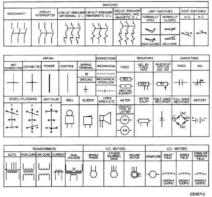
When your car decides to play dead, or a new accessory stubbornly refuses to light up, the first line of defense often involves staring down a bewildering spaghetti of wires. But for the seasoned mechanic, the DIY enthusiast, or anyone who wants to truly understand their vehicle's electrical heart, those seemingly chaotic lines and shapes in a service manual aren't a mess—they're a precise, universal language. Master the art of Automotive Wiring Diagram Symbols, and you'll unlock the secrets to troubleshooting, repairing, and even upgrading your vehicle's complex electrical systems with confidence.
These diagrams aren't just for pros; they're the ultimate guide to understanding how every electrical component in your car interacts. From diagnosing a pesky headlight issue to tracing an intermittent short circuit, learning to read these symbols is the single most empowering skill you can acquire for automotive electrical work.
At a Glance: Key Takeaways for Decoding Wiring Diagrams
- Symbols are Universal: Most automotive symbols adhere to international standards, making them consistent across manufacturers and regions.
- Power Flow: Diagrams typically read from left to right or top to bottom, illustrating how power flows from the battery through components and back to ground.
- Ground is Key: Almost every circuit needs a ground connection; look for the ground symbol everywhere.
- Fuses and Relays are Common: Understand their symbols and functions, as they are central to most circuits.
- Trace the Path: Mentally (or physically, with a highlighter) follow the circuit path from power source to component to ground.
- Context Matters: Always refer to the legend or key provided with a specific manufacturer's diagram, as subtle variations can exist.
Why Bother with Symbols? The Universal Language of Vehicle Electrics
Imagine trying to read a blueprint for a house where every window, door, and wall was described in text. Inefficient, right? Automotive wiring diagrams face the same challenge. Vehicles today are essentially computers on wheels, crammed with hundreds of electrical components, sensors, and actuators. Describing each one in words would create an unwieldy, impossible-to-read document.
That's where symbols come in. They are universally recognized shorthand, a common visual language for electricians and technicians worldwide. Learning these symbols is akin to learning a new alphabet—once you know it, you can read countless "books" (wiring diagrams) and understand the intricate "stories" (electrical circuits) they tell. This shared language minimizes ambiguity, speeds up diagnosis, and ensures consistency, whether you're working on a Ford, a Fiat, or a Ferrari.
The Foundational Elements: Power, Ground, and Wires
Every electrical circuit, no matter how complex, starts with power, moves through components, and returns to ground via a conductor (wire). Understanding how these basic elements are depicted is your first step to Understanding wiring diagram symbols.
Power Sources: Where the Juice Comes From
- Battery: This is usually the easiest to spot, often depicted as a series of long and short parallel lines, with the longer line indicating the positive (+) terminal and the shorter line the negative (-) terminal. You'll typically see "12V" or "BATT" nearby.
- Fuse: A critical safety device. The fuse symbol is commonly a rectangle with a wavy line or an S-curve inside. Sometimes, it's just a simple rectangle with lines on either side. It indicates a sacrificial link designed to blow and protect the circuit from overcurrent.
- Circuit Breaker: Similar in function to a fuse but resettable. Its symbol often looks like a rectangle with a diagonal line passing through it, sometimes with a small, curved line indicating the thermal element.
- Ignition Switch: Often shown as a multi-position switch (e.g., OFF, ACC, RUN, START) with multiple terminals connecting to different circuits depending on the key position.
Ground: The Return Path
- Chassis Ground: Represented by three progressively shorter parallel lines, or an inverted triangle. This signifies a connection to the vehicle's metal chassis or body, which acts as a common return path for many circuits.
- Engine Ground: Similar to chassis ground, but might be indicated with a slightly different variation or text "ENG GND" to denote a specific ground point on the engine block.
Wires and Connections: The Circuit's Pathways
- Wire: A simple straight line. Often, these lines will have labels next to them indicating wire color (e.g., "RED," "BLK/WHT" for black with a white stripe) and sometimes gauge (thickness).
- Connected Wires: When two wires cross and are electrically connected, a small dot is placed at the intersection. Think of it as a knot tied in two ropes.
- Unconnected Wires: When wires cross on a diagram but are not electrically connected, there is no dot. One line typically "jumps" over the other with a small curve or arc.
- Splice: A point where multiple wires are permanently joined together. Often depicted as a dot, sometimes with a specific symbol indicating multiple wires converging.
- Connector/Terminal: These represent multi-pin electrical connectors, often shown as two rectangular blocks with lines entering and exiting, sometimes numbered to correspond to pin positions.
Controlling the Flow: Switches and Relays
These components are the decision-makers of an electrical system, opening and closing circuits to control power to various devices.
Switches: Manual Control
Switches come in many forms, each with a specific purpose:
- SPST (Single Pole, Single Throw): The most basic "on/off" switch. Think of a light switch at home. Its symbol has one input (pole) and one output (throw). When closed, it completes the circuit.
- SPDT (Single Pole, Double Throw): A "changeover" switch. One input can be connected to one of two outputs. Imagine a high/low beam switch for headlights. Its symbol shows one pole swinging between two throws.
- DPST (Double Pole, Single Throw) & DPDT (Double Pole, Double Throw): These are essentially two SPST or SPDT switches operating simultaneously, often used when you need to switch multiple circuits at once with a single action.
- Push-Button (Momentary):
- Normally Open (NO): Circuit is open until you press the button (e.g., horn button). Symbol shows an open contact that closes when actuated.
- Normally Closed (NC): Circuit is closed until you press the button (less common for automotive user controls, but found in some sensors). Symbol shows a closed contact that opens when actuated.
- Toggle/Rocker Switch: Often visually represented like an SPST or SPDT, but the physical shape implies its operation.
Relays: Power Amplifiers
Relays are electromagnetic switches that use a small control current to switch a much larger load current. They are ubiquitous in modern vehicles for components like headlights, fuel pumps, and cooling fans.
- Basic Relay (SPST-NO): Typically shown as a coil (represented by a series of loops or a rectangle) which, when energized, pulls an armature to close a normally open contact.
- SPDT (Changeover) Relay: Similar to the SPST relay but includes both a normally open (NO) and a normally closed (NC) contact. When the coil is de-energized, power flows through the NC contact. When energized, power switches to the NO contact. These are common 5-pin automotive relays.
Understanding relays is crucial because they separate the low-current control circuit (e.g., from a dashboard switch) from the high-current power circuit (e.g., to a motor).
Making Things Go: Actuators and Outputs
These are the components that actually do something in response to electrical signals.
- Motor: A circle with an 'M' inside, sometimes with arrows indicating direction of rotation or internal brushes. This could be a window motor, wiper motor, or cooling fan motor.
- Solenoid: A coil symbol, often with an arrow indicating the mechanical action. Common in fuel injectors, door lock actuators, and starter solenoids.
- Lamp/Bulb: A circle with a cross inside, or sometimes a loop resembling a filament. Used for headlights, taillights, interior lights.
- LED (Light Emitting Diode): A diode symbol (triangle with a line) with two arrows pointing away from it, indicating light emission.
- Heater: A zigzag line, similar to a resistor, but often specifically labeled or depicted in context (e.g., rear defroster).
- Buzzer/Horn: A box or circle with a specific waveform or bell-like symbol inside.
Watching and Sensing: Input Devices
Sensors are the vehicle's "eyes and ears," converting physical conditions (temperature, pressure, speed, position) into electrical signals that the control modules can understand.
- General Sensor: Often depicted as a box or circle with input/output lines, and sometimes an 'S' inside. More specific sensors might use unique symbols or be labeled by type (e.g., "ECT Sensor" for Engine Coolant Temperature).
- Potentiometer (Variable Resistor): A zigzag line with an arrow pointing to it, indicating an adjustable resistance. Used in throttle position sensors or fuel level senders.
- Thermistor (Temperature Sensor): A resistor symbol with a diagonal line through it, often with a 'T' or a curved line. Resistance changes with temperature.
- Hall Effect Sensor: Often a box with 'H' or a specific symbol indicating a semiconductor device sensitive to magnetic fields, used for speed sensing or crankshaft/camshaft position.
Protecting the System: Diodes and Circuit Breakers
Beyond fuses, other components protect the electrical system or direct current flow.
- Diode: A triangle with a line at its apex. Diodes allow current to flow in one direction only (from the base of the triangle to the line, conventionally called anode to cathode). They protect components from reverse voltage spikes and can be used for rectification.
- Zener Diode: Similar to a regular diode, but the line at the apex has small "hooks" on it. Zener diodes are designed to allow current to flow in reverse once a certain voltage (Zener voltage) is reached, useful for voltage regulation.
- Capacitor: Two parallel lines or plates. Stores electrical energy in an electric field. Less common as discrete components in automotive wiring diagrams for general understanding, but fundamental to control modules.
- Inductor/Coil: A series of loops. Stores energy in a magnetic field. Found in ignition coils, solenoids, and some filter circuits.
Connecting It All: Splices and Connectors
How wires meet and part ways is critical for understanding circuit continuity and potential failure points.
- Splice: A dot where multiple lines converge. These are permanent connections made by crimping or soldering wires together.
- Multi-Pin Connector: Depicted as two opposing rectangles or shapes, with numbered lines (pins) entering and exiting. These represent removable connections, often with locking tabs. Pin numbers are crucial for diagnostics.
- Bus Bar: A thick line or bar from which multiple circuits draw power, representing a common distribution point.
The Brains: Control Modules
Modern vehicles are managed by a network of electronic control units (ECUs), often called modules.
- Control Unit/Module (ECU, PCM, BCM, etc.): Typically a large rectangle or box on the diagram, with many input and output lines connected to it. These lines are usually labeled with pin numbers and functions. Inside the box, internal logic is rarely shown, as it's software-driven. This symbol represents the "brain" for a specific system (e.g., Engine Control Unit, Body Control Module).
Decoding a Diagram: A Step-by-Step Approach
Now that you know the symbols, how do you put it all together? Think of a wiring diagram as a map, and your circuit as a journey.
- Identify the System: Start by locating the component or system you're interested in (e.g., headlights, power windows, fuel pump).
- Locate the Power Source: Find where the circuit draws power, usually from the battery or an ignition-switched power source (often through a fuse). Follow the positive (+) path.
- Trace the Path Through Protective Devices: Does the power go through a fuse or circuit breaker first? If so, note its location and rating.
- Follow Through Switches and Relays: Trace the path through any switches (ignition, manual, pressure, etc.) and relays. Understand when these components would allow current to pass. If it's a relay, identify its coil control circuit and its load circuit.
- Identify the Load: Find the component that performs the work (motor, lamp, solenoid). This is your destination.
- Find the Ground: Trace the path from the load back to a ground point. Every functional circuit needs a return path to ground.
- Note Wire Colors and Numbers: Diagrams often label wires with colors (e.g., BLK/YEL for black with a yellow stripe) and sometimes circuit numbers. These are invaluable for physically tracing wires in the vehicle.
- Look for Connectors: Pay attention to any connectors (multi-pin plugs) in the circuit path. These are common points of failure and crucial for testing.
Common Headaches and How to Avoid Them
Even with a good grasp of symbols, diagrams can be tricky.
- Manufacturer Variations: While core symbols are standard, manufacturers sometimes use slightly different conventions for complex components or introduce unique symbols. Always check the legend or key for the specific diagram you're using.
- Overlapping Circuits: A single diagram might show multiple related circuits, making it look busy. Focus on one specific circuit at a time. Highlight it if you're working on a printed copy.
- Multiple Pages: A single system might span several pages. Ensure you follow cross-references (page numbers, connector IDs) diligently.
- Component Location Diagrams: Wiring diagrams tell you how components are connected, but not always where they are physically located. You'll often need a separate "component location diagram" or "connector view" to find the actual part in the car.
- Ground Path Assumptions: Don't assume a component is grounded just because it's bolted to the chassis. Always trace the explicit ground path on the diagram. Poor grounds are a huge cause of electrical headaches.
Beyond the Basics: Context and Conventions
Beyond individual symbols, understanding common diagram conventions helps immensely.
- Power Distribution: Often, diagrams start with a main power distribution block or fuse box, showing power branching off to various circuits.
- Control Modules: When a wire enters a control module (ECU, BCM), it usually represents an input signal. When a wire exits, it's typically an output signal or power supplied by the module. Pin numbers are crucial here for testing.
- Serial Data Lines: Modern vehicles use communication networks (like CAN bus) to allow modules to talk to each other. These are often shown as twisted pairs of wires, sometimes labeled "CAN HI" and "CAN LO" or similar.
- Connectors are Critical: Many faults occur at connectors due to corrosion, loose pins, or broken wires. Diagrams show their pinouts, allowing you to check continuity or voltage at specific points.
Empowering Your Diagnostics: From Diagram to Dashboard
Learning automotive wiring diagram symbols isn't just an academic exercise; it's a direct path to becoming a more capable and confident troubleshooter. Instead of blindly probing wires, you'll approach diagnostics with a clear strategy, knowing exactly what voltage or signal to expect at each point in the circuit.
Next time an electrical problem surfaces, don't reach for the brute force approach. Grab that wiring diagram. With your newfound understanding of the symbols, you'll be able to identify the power source, trace the circuit path, pinpoint the faulty component, and accurately diagnose the issue. You’ll transform from guessing to knowing, saving time, money, and a lot of frustration. It’s an indispensable skill that truly puts you in the driver’s seat of your vehicle's electrical health.