Ever stared at an electrical diagram and felt like you were looking at ancient hieroglyphs? You're not alone. The world of electricity, with all its intricate dance of current and voltage, relies on a precise visual language to function safely and efficiently. Understanding these common electrical wiring symbols isn't just for electricians; it's a vital skill for anyone from DIY enthusiasts tackling a home improvement project to professionals troubleshooting complex industrial systems. These symbols are the universal shorthand for components, connections, and functions, ensuring everyone involved speaks the same language, no matter where they are.
Think of it as learning the alphabet before you can read a book. Each symbol holds a specific meaning, outlining the path electricity takes and how devices interact. Mastering them unlocks the ability to interpret existing systems, design new ones, and diagnose problems with confidence, saving you time, frustration, and potentially, preventing dangerous mistakes.
At a Glance: Key Takeaways for Decoding Electrical Diagrams
- Symbols are a universal language: Standardized graphics represent electrical components and connections globally.
- Safety and clarity are paramount: They ensure precise instructions for installation, repair, and design.
- Context is king: Always look for a diagram's legend to confirm specific symbol interpretations.
- Key indicators guide you: Dots show connections, lines jumping indicate no connection, and special arrows denote direction or adjustability.
- Practice makes perfect: Familiarity comes from regularly reviewing and applying your knowledge to real-world diagrams.
The Unseen Language of Electricity: Why Symbols Matter
In a world buzzing with unseen electrons, clarity is paramount. Electrical wiring symbols provide that clarity, acting as the foundation for all electrical design and maintenance. Without them, every circuit would be a bespoke, handwritten set of instructions, leading to chaos, errors, and significant safety hazards.
These graphical representations are far more than mere pictures; they're a concise, information-rich language. For engineers, they streamline the design process, allowing complex systems to be mapped out logically. For electricians, they offer a clear roadmap for installation and troubleshooting, ensuring every wire goes to the right place and every component performs its intended function. This standardized "shorthand" is critical for:
- Accurate Communication: Everyone, from the designer to the installer to the repair technician, understands the blueprint exactly.
- Enhanced Safety: Clearly identified components and pathways help prevent miswiring that could lead to shocks, fires, or equipment damage.
- Efficient Troubleshooting: When something goes wrong, a clear diagram with standard symbols allows for quick identification of the faulty component or connection.
- Global Understanding: Whether you're in New York or New Delhi, a resistor symbol looks the same, fostering international collaboration and component compatibility.
- Streamlined Design and Documentation: They speed up the creation of new systems and make documentation straightforward and easy to update.
Ultimately, electrical symbols empower you to look beyond the physical wires and components, seeing the circuit as a functional system. They're the cornerstone of competence in any electrical endeavor.
Decoding the Diagram: How to Read Electrical Symbols
Reading an electrical diagram isn't about memorizing every single symbol (though you'll quickly recognize the common ones). It's about understanding the core principles that govern this visual language. Think of it as learning grammar rules rather than just vocabulary.
Here’s how to approach a diagram and make sense of the symbols within it:
- Start with the Legend: Every good electrical schematic or wiring diagram should come with a legend or key. This is your absolute first stop. While many symbols are universal, variations exist, and proprietary symbols might be used. The legend clarifies exactly what each symbol means in that specific diagram.
- Understand Connections and Non-Connections:
- Connected Wires: A single dot at the junction of two or more wires signifies they are electrically connected. Current can flow between them.
- Not Connected Wires: When one wire crosses another without a dot, it means they are simply passing over each other, with no electrical connection between them. Sometimes this is shown as a "jump" or "bridge" where one line arches over the other.
- Identify Polarity and Current Type:
- DC Polarity: Plus (+) and minus (−) symbols clearly indicate direct current (DC) polarity. Batteries, for instance, have distinct positive and negative terminals.
- AC Current: A wave symbol (~) typically represents alternating current (AC) voltage or current, common in household power.
- Direction of Flow: Arrows placed along a wire or within a component (like a diode) indicate the intended or typical direction of current flow. This is particularly crucial for components that are sensitive to current direction.
- Adjustability: A diagonal arrow drawn through or over a component often signifies that its value is adjustable or variable. For example, a resistor with a diagonal arrow is a variable resistor (potentiometer).
- Measuring Instruments: A letter inside a circle often denotes a measuring instrument. 'V' for Voltmeter, 'A' for Ammeter, 'Ω' for Ohmmeter.
- Component Specifics: Diodes, transistors, and operational amplifiers often use triangular shapes within their symbols to indicate the direction of current flow or signal processing. These shapes are integral to understanding their function.
By combining these general rules with the diagram's specific legend, you'll be well on your way to confidently interpreting even complex electrical blueprints. If you're looking to dive deeper into the general world of diagrams, you might want to explore wiring diagram symbols more broadly.
Your Essential Guide to Common Electrical Wiring Symbols
Let's break down the most frequently encountered electrical wiring symbols into logical categories. This section will serve as your quick-reference dictionary for the electrical language.
A. Wires: The Circuit's Highways
Wires are the arteries of any electrical system, conducting electricity from one point to another. Their symbols indicate connections, disconnections, and special linking methods.
- Electrical Wire: A simple straight line. This is the most basic representation of a conductor.
- Connected Wires: Two or more lines intersecting with a solid dot at the junction. This unmistakably means they are electrically joined.
- Not Connected Wires: Two lines crossing without a dot, or one line "jumping" over the other (an arc). This indicates that the wires physically cross but do not make electrical contact.
- Jumper: Often shown as a small, curved line, or a segment of wire with specific connection points. Used to temporarily or permanently close a connection.
- Solder Bridge: A small, filled-in arc or dot connecting two traces on a PCB, indicating a connection made by soldering.
B. Grounds: Your Circuit's Safe Harbor
Grounds are fundamental for safety and signal integrity, providing a reference point and a path for fault currents.
- Earth Ground: Three parallel lines of decreasing length. This symbol represents a direct connection to the physical earth, providing a safe path for fault currents and a common reference potential for many systems. Essential for protection against electrical shock.
- Chassis Ground: A solid triangle or a series of concentric arcs. This connects to the metal enclosure or frame of a circuit or device, which may or may not be directly connected to earth ground. It serves as a common return path for currents within the device.
- Digital/Analog Grounds (Common Ground): Often depicted as a chassis ground, sometimes with specific labels like "AGND" or "DGND." Used to provide separate, decoupled grounding systems for analog and digital signals within a circuit to minimize noise interference.
C. Sources: Where the Power Begins
Sources provide the energy that drives the circuit, whether it's a steady battery or an oscillating AC supply.
- Voltage Source: A circle with a plus (+) and minus (−) sign inside, or a series of long and short parallel lines (like a battery, but often without the explicit battery label). Provides a constant voltage.
- Current Source: A circle with an arrow inside, indicating the direction of current flow. Provides a constant current.
- AC Voltage Source: A circle with a wavy line (~) inside. This represents an alternating current voltage supply, such as standard wall power.
- Battery/Battery Cell (Single-Cell): Two parallel lines of unequal length, with the longer line representing the positive terminal and the shorter line the negative.
- Multi-Cell Battery: Multiple pairs of unequal parallel lines, indicating several battery cells connected in series to provide a higher voltage.
- Generator: A circle with a wavy line inside (like AC voltage source) and sometimes an "G" or an "M" for mechanical input. Transforms mechanical energy into electrical energy.
- Controlled Voltage Source: A diamond shape with a plus (+) and minus (−) sign inside. The output voltage is controlled by another voltage or current elsewhere in the circuit.
- Controlled Current Source: A diamond shape with an arrow inside. The output current is controlled by another voltage or current.
D. Switches & Relays: Guiding the Flow
Switches and relays control the flow of electricity, acting as on/off gates or routing devices.
- SPST (Single Pole, Single Throw) Toggle Switch: A simple lever arm that opens or closes a single circuit. "Single pole" means one circuit is controlled, "single throw" means it has one "on" position.
- SPDT (Single Pole, Double Throw) Toggle Switch: A lever arm that connects a single common terminal to one of two other terminals. This allows you to select between two connections or isolate one of two circuits.
- Push Button Switch (N.O. - Normally Open): Two contacts that are open (no connection) until the button is pressed, momentarily closing the circuit.
- Push Button Switch (N.C. - Normally Closed): Two contacts that are closed (connected) until the button is pressed, momentarily opening the circuit.
- DIP Switch: A rectangular block representing multiple miniature SPST switches, often used for configuring electronic devices.
- SPST Relay: An electromagnet coil (represented by a rectangle or coil symbol) controls a single pole, single throw switch. When the coil is energized, it closes the contacts, allowing current to flow.
- SPDT Relay: Similar to an SPST relay, but the electromagnet controls a single pole, double throw switch, allowing it to switch a common contact between two different outputs when activated. Understanding these control components is key when you're troubleshooting electrical circuits. Troubleshooting electrical circuits often involves checking the state of switches and relays.
E. Passive Components: Shaping the Current
These are fundamental components that don't generate power but modify it in various ways.
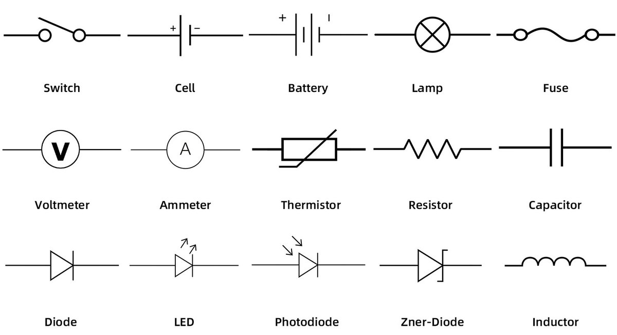
- Resistor: A zigzag line or a rectangle. Resistors impede the flow of electrical current, used to control current levels, divide voltage, or dissipate energy. A diagonal arrow through it indicates a variable resistor (potentiometer).
- Fuse: A small rectangle with a line running through it, or a specific "S" shape. Fuses are safety devices designed to melt and break the circuit when current exceeds a safe level, protecting other components from damage.
- Lamp or Light Bulb: A circle with a cross inside, or a loop symbol. Generates light when current flows through it.
F. Inductors: Storing Magnetic Energy
Inductors store energy in a magnetic field when current flows through them.
- Simple Inductor: A series of curved segments resembling a coil. Used in filters, chokes, and resonant circuits.
- Iron-Core Inductor: A coil symbol with two parallel lines drawn alongside it, representing an iron core used to enhance inductance.
- Variable Inductor: An inductor symbol with a diagonal arrow through it, indicating that its inductance can be adjusted.
G. Electromechanical Devices: Power in Motion and Sound
These devices convert electrical energy into mechanical motion or sound.
- Motor: A circle with an "M" inside, or a circle with an "M" connected to two or three lines for input. Transforms electric power into mechanical motion.
- Speaker: A circle with a cone-like shape inside, or two radiating arcs. Produces sound waves from electrical signals.
- Buzzer: A circle with "Z" or an exclamation mark, often with radiating lines. Emits a buzzing tone.
- Bell: A bell-shaped symbol. Activates a mechanical ringer.
- Heater: A zigzag line or a coil-like symbol with arrows indicating heat dissipation. Transforms electric power into heat.
H. Installation Devices & Outlets: Connecting to the World
These symbols represent the fixed infrastructure components and connections found in buildings. When engaging in residential wiring basics, you'll encounter many of these.
- Electrical Switch Box: A simple rectangle, sometimes with an "S" inside. Represents a box designed to house switches.
- Circuit Breaker: A rectangle with a diagonal line (sometimes with a curve) and a small rectangle or line indicating the trip mechanism. Automatically trips to break the circuit and stop the flow of electricity when an overload or short circuit occurs.
- Specific Outlets:
- Dishwasher Outlet: A circle with a "DW" inside.
- Fan Outlet: A circle with an "F" inside.
- TV Outlet: A circle with "TV" or an antenna symbol.
- Exhaust Fan: A fan symbol with an "X" or "EXH" sometimes.
- Water Heater Outlet: A circle with "WH" inside.
- Telephone Jack Outlet: A circle with "T" or a telephone handset symbol.
- Junction Box: A circle with lines coming into it, sometimes an "J" inside. Installs a junction box where wires are spliced or connected.
- Electrical Panel, Distribution Box: A large rectangle, often with lines indicating connections to multiple circuits, sometimes "EP" or "DB" inside. The main point of electrical power distribution in a building.
- Building Devices:
- Thermostat: A circle with "T" or specific thermostat symbol.
- Air Condition: An "AC" symbol or a specific unit symbol.
- Fire Alarm: A bell or horn symbol with "F" or "FA."
- Alarm: A bell or horn symbol, often with "AL."
- Doorbell: A bell symbol, sometimes with "DB."
- Smoke Detector: A circle with an "S" or "SD" or a specific smoke detector icon.
This comprehensive list covers the vast majority of symbols you'll encounter. While this guide provides a strong foundation, remember that the field of electrical components is vast; exploring different types of electrical components will deepen your understanding even further.
Beyond the Basics: Best Practices for Using and Interpreting Symbols
Simply knowing what each symbol means is a great start, but becoming truly proficient involves adopting a few best practices.
Always Refer to the Diagram's Legend
We can't stress this enough. While international standards like IEC (International Electrotechnical Commission) and ANSI (American National Standards Institute) provide widely accepted symbols, slight variations can exist. Some manufacturers even use proprietary symbols for unique components. The legend is your definitive guide for that specific diagram. If a legend is missing, proceed with extreme caution and seek clarification.
Understand Regional and Industry Standards
Be aware that electrical symbols can vary slightly by region (e.g., European vs. North American standards) or by specific industry (e.g., automotive vs. residential vs. industrial control). If you're working with diagrams from a different context than your usual, double-check the applicable standards. This is particularly important for tasks involving DIY home electrical projects where older or non-standard diagrams might pop up.
Safety First: The Real-World Impact of Symbols
Misinterpreting a symbol isn't just an inconvenience; it can be incredibly dangerous. Connecting a wire to the wrong terminal, bypassing a safety device, or misjudging a power source can lead to electrical shock, fire, or catastrophic equipment failure. Always confirm your understanding, especially when dealing with live circuits or high voltages. This level of attention to detail is a fundamental aspect of understanding electrical safety.
Attribution and Usage Rights
If you're creating or publishing diagrams using existing symbol libraries, always be mindful of copyright and licensing. Many symbol sets are freely available, but others may require attribution or specific usage permissions. Check the terms associated with any symbol library you utilize. Misleading or misrepresenting technical information through symbol usage should always be avoided.
The Pitfalls of Outdated or Poorly Drawn Diagrams
Sometimes, you'll encounter diagrams that are old, poorly drawn, or incomplete. In such cases, rely on your understanding of circuit theory and, if possible, physical inspection of the actual wiring. Never make assumptions. When in doubt, consult an expert.
Taking Your Skills Further: Continuous Learning
Mastering common electrical wiring symbols is a journey, not a destination. The world of electronics and electrical systems is constantly evolving, with new components and standards emerging regularly.
To truly solidify your understanding and grow your expertise:
- Practice Regularly: The more diagrams you read, the more intuitive the symbols will become. Look up schematics for common household appliances, automotive systems, or electronic gadgets.
- Build Simple Circuits: Hands-on experience helps bridge the gap between theoretical symbols and physical reality. As you connect real wires and components, their symbolic representations will make more sense.
- Invest in Good Reference Materials: Keep a reliable handbook or online resource for electrical symbols handy.
- Stay Curious: Whenever you see an unfamiliar symbol, take the time to look it up and understand its function.
By consistently applying these practices, you'll not only read electrical diagrams but truly understand the intricate systems they represent, empowering you to work more safely, efficiently, and effectively with the power that lights up our world.