It might look like a jumble of abstract squiggles, lines, and boxes, but every icon on an electronic circuit diagram tells a crucial story. Welcome to the world of Electronic Circuit Symbols Explained, your essential guide to understanding the universal language of electronics. Mastering these symbols isn't just about memorizing shapes; it's about unlocking the secrets behind how gadgets work, empowering you to design, troubleshoot, and innovate with confidence. Think of it as learning the alphabet before writing a novel – these symbols are the building blocks of every circuit you'll ever encounter.
Ready to demystify the blueprint of modern technology? Let’s dive in.
At a Glance: Your Quick Guide to Circuit Symbols
- Universal Language: Symbols follow international standards (like IEEE Std 315) for clarity.
- Efficiency: They simplify complex components into easy-to-draw pictograms.
- Core Functions: Symbols represent everything from simple wires to complex transistors.
- Essential for Design: Crucial for reading schematics, designing new circuits, and troubleshooting existing ones.
- Practice Makes Perfect: Familiarity comes with repeatedly seeing and using these symbols in various contexts.
Why Electronic Circuit Symbols Are Your Superpower
Imagine trying to build a house without a blueprint, or assemble a complex engine without a diagram. In electronics, that blueprint is the circuit diagram, and the language it speaks is through these symbols. Instead of drawing a detailed, photorealistic resistor, which would be time-consuming and clutter a diagram, we use a simple, standardized squiggle. This not only speeds up the design process but also makes diagrams universally readable by engineers and hobbyists alike, regardless of spoken language.
These pictograms abstract the real-world complexity of components into their fundamental electrical function. A capacitor, whether it's a tiny ceramic disc or a large electrolytic can, is still represented by two parallel lines, signifying its ability to store charge. Understanding this shorthand is your first step towards truly understanding electronics – from the simplest LED blinker to the most intricate microprocessor. For a broader understanding of how these symbols fit into the larger design process, consider this Guide to wiring diagram symbols.
The Foundation: Connecting Your Circuit
Before you can build anything complex, you need to understand the basics of connection and flow. These symbols represent the absolute groundwork of any electronic circuit.
Wires: The Lifelines of Your Circuit
Wires are the highways of electron flow, connecting different components. On a diagram, they're typically represented by simple lines, but how those lines interact tells a critical story.
- Wire:
- Symbol: A straight line.
- What it does: Physically connects two points, allowing current to flow between them.
- In practice: These are your copper traces on a PCB, or the jumper wires on a breadboard.
- Wires Joined:
- Symbol: Two or more lines intersecting with a solid dot at the junction.
- What it does: Indicates that these wires are electrically connected. Current can flow freely between all wires at this point.
- Common pitfall: Always look for the dot! A crossing without a dot means no connection.
- Wires Not Joined:
- Symbol: Two lines crossing over each other without a dot. One line might have a small "hop" arc over the other.
- What it does: Shows that wires are physically crossing on the diagram but are not electrically connected. Think of it like an overpass on a highway.
- Why it matters: Crucial for avoiding unintended short circuits or incorrect signal paths.
Ground (GND): The Circuit's Reference Point
Ground is more than just "earth"; it's the common reference point, often zero volts (0V), for all voltages in a circuit.
- Ground (GND):
- Symbol: A series of decreasing horizontal lines, or sometimes a downward-pointing triangle.
- What it does: Provides a common return path for current and a reference voltage (typically 0V). For mains or radio, it can represent an actual connection to the earth.
- Practical tip: Most components will have one connection leading to ground. It's the "home" for your electrons.
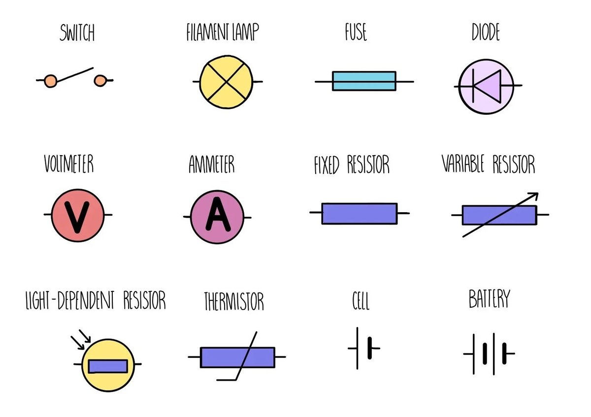
Switches: Controlling the Flow
Switches are your circuit's gatekeepers, opening or closing paths for current.
- Switch (SPST - Single-Pole, Single-Throw):
- Symbol: A line with a pivot point, and another line that can swing to connect/disconnect. Often depicted in the open (OFF) position.
- What it does: A basic on/off switch. "Single-pole" means it controls one circuit, "single-throw" means it has one "on" position.
- Use cases: Turning a light on or off, powering up a device.
- ON-OFF-ON SPDT Switch (Single-Pole, Double-Throw):
- Symbol: A line with a pivot, and two possible connection points.
- What it does: Controls one circuit ("single-pole") but can connect it to one of two different paths ("double-throw"). An "ON-OFF-ON" variant means it has a central off position.
- Use cases: Selecting between two different functions, like choosing high or low fan speed, or directing a signal to one of two destinations.
Powering Your Projects: Energy Sources
Every electronic circuit needs a source of energy. These symbols represent how that energy is supplied, whether it's a small battery or grid power.
DC Power: Steady Energy
Direct Current (DC) sources provide a constant flow of electricity in one direction.
- Cell:
- Symbol: Two parallel lines, one long and one short. The long line is always the positive (+) terminal, and the short line is the negative (-) terminal.
- What it does: A single unit that provides electrical energy, like a single AA battery.
- Important: The symbol doesn't indicate voltage, so you'll often see "1.5V" or "3V" written next to it.
- Battery (B):
- Symbol: Multiple cell symbols stacked together (typically two or more sets of long/short lines). Again, the longest line on one end is positive.
- What it does: Comprises multiple cells to supply a higher or more sustained electrical energy.
- Examples: A 9V battery symbol shows several cell representations.
AC Power: Alternating Energy
Alternating Current (AC) changes direction periodically and is what powers our homes and businesses.
- AC Supply:
- Symbol: A circle with a wavy line (a sine wave) inside.
- What it does: Represents an Alternating Current power source, where the voltage and current direction continuously reverse. This is your wall outlet power.
- Understanding: Unlike DC, which has fixed positive and negative, AC cycles between polarities.
- Transformer (T):
- Symbol: Two coils (often depicted as squiggly lines or loops) separated by a dashed or solid line (representing an iron core). No direct electrical connection between the coils.
- What it does: Used to step up (increase) or step down (decrease) AC voltages. It doesn't work with DC. The lack of physical connection provides electrical isolation.
- Applications: Power adapters, power supplies, transmitting electricity over long distances.
Shaping the Flow: Passive Components
Passive components don't generate power but rather store, dissipate, or manipulate it. They are fundamental to almost every circuit.
Resistors (R): Controlling Current
Resistors are perhaps the most common component, used to limit current or divide voltage.
- Resistor (R):
- Symbol: A zigzag line (US standard) or a rectangular box (European standard).
- What it does: Resists the flow of electric current, converting electrical energy into heat.
- Key use: Crucial for protecting sensitive components like LEDs from excessive current.
- Potentiometer (POT):
- Symbol: A standard resistor symbol with an arrow pointing to the resistive element, indicating a variable tap.
- What it does: A 3-terminal variable resistor. By turning a knob or sliding a lever, you change the resistance between the middle terminal (wiper) and the outer terminals.
- Applications: Volume control, dimmers, sensor input (e.g., joystick position).
Capacitors (C): Storing Charge
Capacitors are like tiny batteries that can quickly store and release electrical energy.
- Capacitor (C):
- Symbol: Two parallel lines of equal length, separated by a gap.
- What it does: Stores electrical energy in an electric field between two conductor plates separated by a dielectric material.
- Uses: Filtering noise, timing circuits (when paired with a resistor), blocking DC signals while allowing AC signals to pass.
- Polarized Capacitor:
- Symbol: One plate is straight, the other is curved, with a plus (+) sign indicating the positive terminal. Sometimes the straight line also has a minus (-) sign.
- What it does: Stores electric charge, but must be connected with the correct polarity (positive to positive, negative to negative) to prevent damage or explosion.
- Important: Typically electrolytic or tantalum capacitors.
- Variable Capacitor:
- Symbol: A standard capacitor symbol with an arrow diagonally crossing through it.
- What it does: Its capacitance can be changed, usually by rotating internal plates (often air-dielectric).
- Applications: Tuning circuits in old radio receivers and transmitters for frequency selection.
- Trimmer Capacitor:
- Symbol: A variable capacitor symbol with a "T" or "screwdriver" arrow, implying infrequent adjustment.
- What it does: A type of variable capacitor designed for fine-tuning a circuit, usually adjusted once during calibration with a small screwdriver and then left alone.
- Applications: Precisely calibrating RF circuits.
Inductors: Storing Magnetic Energy
Inductors are coils of wire that store energy in a magnetic field.
- Inductor:
- Symbol: A series of coiled loops or humps, sometimes with parallel lines (solid or dashed) next to it if it has an iron core.
- What it does: Resists changes in current flow by storing energy in a magnetic field.
- Applications: Filters, chokes, tuned circuits, power supply regulation.
Directing the Current: Diodes
Diodes are semiconductor devices that allow current to flow primarily in one direction.
- Rectifier Diode (Silicon Diode):
- Symbol: A triangle pointing to a line. The triangle is the anode (positive, where current enters), and the line is the cathode (negative, where current exits).
- What it does: Acts as a one-way valve for electrical current, allowing it to flow from anode to cathode when forward-biased.
- Uses: Converting AC to DC (rectification), protection against reverse voltage spikes.
- LED (Light-Emitting Diode):
- Symbol: A standard diode symbol with two arrows pointing away from it, representing emitted light.
- What it does: A transducer that converts electrical energy into light very efficiently.
- Everywhere: Indicator lights, displays, lighting.
- Zener Diode (ZD):
- Symbol: A diode symbol where the line (cathode) is shaped like a "Z" or an inverted "S."
- What it does: A special diode designed to allow current to flow in the reverse direction once a specific "breakdown voltage" (Zener voltage) is reached, maintaining a stable voltage across its terminals.
- Uses: Voltage regulation, protecting circuits from overvoltage.
The Brains of the Operation: Transistors
Transistors are the workhorses of modern electronics, acting as electronic switches or amplifiers.
- NPN Transistor (Q):
- Symbol: A circle enclosing a three-legged component. The emitter has an arrow pointing outward from the base. The other two terminals are the collector and base.
- What it does: Amplifies current. A small current and positive voltage applied to its base allows a much larger current to flow from the collector to the emitter.
- Composition: A P-type semiconductor layer sandwiched between two N-type layers (N-P-N).
- PNP Transistor (Q):
- Symbol: Similar to NPN, but the emitter arrow points inward towards the base.
- What it does: Also amplifies current, but typically operates with negative voltages relative to the emitter. A small current out of its base allows a large current to flow from the emitter to the collector.
- Composition: An N-type semiconductor layer sandwiched between two P-type layers (P-N-P).
Sensing the World: Input Components
These components allow electronic circuits to interact with and respond to their environment.
- LDR (Light-Dependent Resistor):
- Symbol: A resistor symbol enclosed in a circle, with two arrows pointing towards it, indicating incident light.
- What it does: A variable resistor whose resistance decreases as light intensity increases.
- Applications: Automatic streetlights, light meters, alarm systems.
- Photodiode:
- Symbol: A diode symbol enclosed in a circle, with two arrows pointing towards it.
- What it does: Converts light energy into an electrical current or voltage. It's essentially a light-sensitive diode.
- Uses: Optical communication, remote controls, solar cells (large scale photodiodes).
- Phototransistor:
- Symbol: A transistor symbol (usually NPN) enclosed in a circle, with two arrows pointing towards the base junction. Sometimes the base lead is not shown, implying light replaces the base current.
- What it does: A light-sensitive transistor that converts light into a base current, thereby controlling the larger collector-emitter current. More sensitive to light than a photodiode.
- Uses: Optical switches, light-activated relays, light sensing.
- Thermistor (TH):
- Symbol: A resistor symbol with a diagonal line and a "T" (for temperature) near it.
- What it does: A temperature-sensitive resistor. Its resistance changes significantly with temperature (either increasing or decreasing).
- Applications: Temperature sensors, thermostats, over-temperature protection.
- XTAL Crystals:
- Symbol: A rectangle with two diagonal lines inside, and two leads extending from the ends.
- What it does: Utilizes the piezoelectric effect (vibration of a crystal) to produce a very precise and stable frequency output signal when used in an oscillator circuit.
- Crucial for: Clocks in microcontrollers, radio transmitters, timing circuits where accuracy is paramount.
Bringing Circuits to Life: Output & Actuator Devices
These components translate electrical signals into tangible outputs like sound, light, or motion.
Audio Outputs
- Speaker:
- Symbol: A circle with two expanding arcs, similar to a megaphone.
- What it does: A transducer that converts fluctuating electrical current into sound waves, typically producing a wide range of audio frequencies.
- Everyday: Radios, phones, alarm systems.
- PiezoTransducer:
- Symbol: A rectangle with two diagonal lines inside, similar to a crystal, but with a speaker-like output symbol next to it.
- What it does: A type of speaker that uses the piezoelectric effect to produce a sharp, often high-pitched, tone.
- Uses: Simple beepers, alarms, basic audible feedback.
- Buzzer:
- Symbol: A circle with an 'X' inside and two expanding arcs, or sometimes a speaker symbol with "BZ" next to it.
- What it does: Produces a loud, often distinct tone, typically at a fixed frequency (e.g., 1500 Hz).
- Common in: Doorbell chimes, warning signals.
- Microphone (MIC):
- Symbol: A circle with an 'X' inside, and two arcs pointing towards it (opposite of a speaker).
- What it does: A transducer that converts sound waves into electrical energy.
- Found in: Phones, recording devices, voice-activated systems.
Visual Outputs
- Lamp Indicator:
- Symbol: A circle with a cross (X) inside.
- What it does: A general symbol for any device that converts electrical energy into light to indicate status (e.g., a warning light).
- Often used: Status indicators, panel lights.
- Globe:
- Symbol: A circle with a loop or coil inside, representing the filament.
- What it does: A simple light source where a fine wire (filament) inside a glass bulb glows when current passes through it.
- Historical context: Incandescent light bulbs.
Motion Output
- Motor (M):
- Symbol: A circle with the letter 'M' inside.
- What it does: A transducer that converts electrical energy into mechanical energy (rotational motion).
- Versatile: Fans, robotic parts, pumps. Can also work in reverse as a generator.
Keeping Track: Measurement Tools
To understand what’s happening in a circuit, you need to measure its electrical properties.
- Voltmeter:
- Symbol: A circle with the letter 'V' inside.
- What it does: Measures the voltage (potential difference) between two points in a circuit. Always connected in parallel across the component or section you want to measure.
- Essential: For checking power supply levels, voltage drops.
- Ammeter:
- Symbol: A circle with the letter 'A' inside.
- What it does: Measures the current flowing through a circuit. Always connected in series with the path where you want to measure current.
- Crucial: For checking component current draw, short circuits.
- Galvanometer:
- Symbol: A circle with the letter 'G' inside.
- What it does: A very sensitive meter used to detect and measure tiny electrical currents, typically in the microampere (µA) or milliampere (mA) range.
- Precision: Used where small currents need to be monitored.
- Ohmmeter:
- Symbol: A circle with the Greek letter Omega (Ω) inside.
- What it does: Measures the electrical resistance of a component or circuit. Usually part of a multimeter.
- Diagnostics: Useful for checking if a component is open, shorted, or has its specified resistance.
The Mighty Fuse: Essential Protection
Safety is paramount in electronics, and the fuse is your first line of defense.
- Fuse (F):
- Symbol: A rectangle with a thin S-shaped line or a rectangular box with a line passing through it that "breaks" in the middle.
- What it does: A safety device containing a thin wire designed to melt or "blow" and break the circuit if the current flowing through it exceeds a specified safe value.
- Protector: Prevents damage to more expensive components or even fires in case of a fault or overload.
Mastering the Language: Tips for Reading Schematics
Now that you've got the alphabet down, how do you read the full story?
- Follow the Power: Start at the power source (battery, AC supply) and trace the path of current through the circuit.
- Identify Key Components: Locate major components like microcontrollers, amplifiers, or sensors first.
- Look for Ground: Ground is your reference point for all voltages; identify where components connect to it.
- Understand Signal Flow: Determine the intended direction of signals, usually from input components (sensors) through processing (transistors, ICs) to output components (LEDs, motors).
- Pay Attention to Labels: Symbols often have associated text labels (e.g., "R1," "C2," "U3") which correspond to a bill of materials and describe the component's value (e.g., "10kΩ," "10µF").
- Don't Rush: Circuit diagrams can be complex. Take your time, trace paths with your finger or a pencil, and understand each section before moving on.
Common Questions & Misconceptions
- "Are circuit symbols universal?"
Mostly, yes! While there are slight regional variations (e.g., US vs. European resistor symbols), major international standards like IEEE Std 315 and IEC 60617 ensure a high degree of commonality. If you understand one standard, you can generally decipher another with minor adjustments. - "Why are some symbols drawn differently in different places?"
Historical conventions and specific engineering fields (e.g., power systems vs. digital electronics) sometimes lead to variations. For instance, some resistor symbols are zigzag lines, others are rectangles. Always check the legend if you're unsure about a specific diagram, but the core function usually remains clear. - "Does the symbol tell me the component's value (e.g., resistor resistance, capacitor capacitance)?"
No, the symbol only tells you the type of component. Its specific value (e.g., 10kΩ for a resistor, 100µF for a capacitor, 5V for a power supply) will always be written next to the symbol on the schematic. - "What's the difference between a cell and a battery symbol?"
A cell represents a single electrochemical unit (like one AA battery). A battery symbol shows multiple cells joined together, indicating a power source made up of two or more cells for a higher voltage or capacity (like a 9V battery). - "How do I know which way current flows?"
Conventional current flow is from positive (+) to negative (-). Diodes have an arrow that indicates this allowed direction. For components like resistors, current flows from higher potential to lower potential.
Your Next Steps in Circuit Design
Congratulations! You've taken a significant leap in understanding the fundamental language of electronics. You now have the tools to look at a circuit diagram and begin to see not just lines and shapes, but a functional system of components working together.
But knowledge is best put into practice. Here’s how you can continue your journey:
- Start Simple: Find basic circuit diagrams online (like an LED blinker or a simple alarm) and try to identify every symbol you've learned today.
- Build a Basic Circuit: Take a breadboard and some simple components. Connect them according to a schematic and see the theoretical come to life.
- Experiment: Change component values (e.g., a different resistor for an LED) and observe the effect. This builds intuition.
- Explore Integrated Circuits (ICs): Once comfortable with discrete components, start looking at datasheets for simple ICs (like op-amps or 555 timers) to see how groups of components are abstracted into single symbols.
The world of electronics is vast and exciting, and your ability to read and understand circuit symbols is your passport to exploring it. Keep learning, keep building, and soon you'll be designing your own electronic creations!