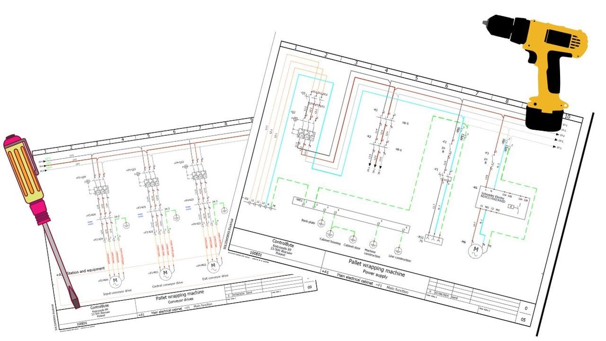
Navigating the intricate world of electrical systems can feel like deciphering a secret language, especially when faced with a tangle of wires and components. But what if there was a master key, a blueprint that laid out every connection, every function, and every potential fault? That's precisely what a wiring diagram offers. Learning how to read, interpret, and troubleshoot wiring diagrams isn't just a skill for electricians; it's a superpower for anyone wanting to understand, repair, or even design electrical circuits confidently.
These visual tools are the unsung heroes of countless projects, from fixing a stubborn appliance to installing a new smart home system or tracing a fault in your car's electrical network. They translate complex power flows into easy-to-follow maps, saving you time, money, and a lot of frustration. More importantly, understanding them helps you avoid dangerous mistakes that could lead to electrical shocks, equipment damage, or even fires.
At a Glance: Key Takeaways for Wiring Diagram Mastery
- Wiring diagrams are visual roadmaps: They show how electrical components connect and power flows.
- Three main types: Schematics (functional), layouts (physical), and single-line (overview).
- Symbols are the language: Learn common symbols for components like resistors, switches, and power sources.
- The legend is your translator: Always check the diagram's key first to understand its specific symbols and labels.
- Follow the power: Trace the flow from the source through the circuit to identify components and connections.
- Troubleshooting is detective work: Use the diagram to isolate faults by testing voltage, continuity, and resistance.
- Practice makes perfect: Start with simple diagrams and gradually work up to more complex ones.
- Safety first: Always disconnect power before working on any electrical system.
Why Wiring Diagrams Are Your Best Electrical Ally
Imagine trying to assemble a complex piece of furniture without instructions, or navigating a foreign city without a map. That's essentially what you're doing when you approach an electrical system without its wiring diagram. These essential documents serve as the DNA of any electrical setup, detailing every wire, every component, and every connection.
They are crucial for several reasons:
- Understanding Complex Systems: Modern electrical systems, whether in a vehicle, a home appliance, or industrial machinery, are incredibly intricate. Diagrams break them down into digestible, logical segments, revealing the intended power flow and component function.
- Efficient Troubleshooting: When something goes wrong, a wiring diagram transforms a daunting task into a methodical investigation. Instead of blindly probing, you can systematically trace circuits, pinpoint potential fault locations, and quickly diagnose issues like open circuits, shorts, or component failures.
- Safe Installations and Repairs: Electrical work carries inherent risks. By providing a clear, accurate representation of the system, diagrams help you ensure that new installations comply with safety rules and building codes, and that repairs are executed correctly, minimizing the risk of electrical shocks, fires, or equipment damage.
- Planning and Design: For engineers and hobbyists alike, diagrams are the starting point for designing new circuits or modifying existing ones. They allow you to visualize changes, anticipate their effects, and ensure proper functionality before a single wire is connected.
Ultimately, mastering wiring diagrams is about gaining control and confidence in the face of electrical complexity. It’s about working smarter, safer, and with greater precision.
Cracking the Code: The Anatomy of a Wiring Diagram
Before you can effectively read, interpret, or troubleshoot, you need to understand the fundamental elements that make up a wiring diagram. Think of it as learning the alphabet and grammar before you can read a book.
Symbols: The Universal Language of Electricity
At the heart of every wiring diagram are symbols. These standardized graphical representations stand in for physical electrical components like resistors, capacitors, switches, batteries, motors, lights, and countless other devices. Each symbol carries a specific meaning, allowing engineers and technicians worldwide to understand the same diagram. For instance, a simple circle with a cross inside typically represents a lamp or light bulb, while a series of parallel lines of varying lengths signifies a battery.
Understanding these symbols is foundational. While many are universally recognized, some specialized or industry-specific diagrams might use unique symbols. That's where the next crucial element comes in. To truly delve into the visual shorthand of electrical design, you can Explore wiring diagram symbols and their common meanings in detail.
Lines & Labels: Tracing the Current's Journey
Lines on a wiring diagram aren't just decorative; they represent wires or conductors, showing the pathways electricity takes through a circuit. These lines often feature labels—letters, numbers, or alphanumeric codes—to indicate their purpose, gauge, or the specific circuit they belong to (e.g., "12V Power," "Ground," "Signal A").
Wire colors also play a vital role, though their conventions can vary significantly by region or application (e.g., automotive vs. residential vs. industrial). Always check the diagram's legend or local standards. For example, in many AC systems, black might indicate live, white neutral, and green or bare copper the ground. In DC systems, red often signifies positive and black negative. Understanding these color codes can dramatically aid in tracing paths and identifying functions quickly in the physical system.
Power Sources & Loads: Where Energy Begins and Ends
Every electrical circuit needs a power source—the point where electricity originates. This could be a battery (DC), an AC power supply, a generator, or a wall outlet. On a diagram, power sources are typically indicated by specific symbols (like the battery symbol mentioned above) or by clear positive (+) and negative (-) or live, neutral, and ground labels.
From the power source, electricity flows to load devices. These are the components that use electricity to perform a function. Examples include light bulbs, motors, heaters, sensors, and electronic modules. Identifying the power source and the various loads helps you understand the diagram's purpose and how energy is being converted or utilized.
Controls & Safety: Switches, Relays, and Grounding
Beyond just powering loads, circuits need control and protection.
- Switches are manual devices that open or close a circuit, allowing or preventing current flow.
- Relays are electrically operated switches, often used to control a high-power circuit with a low-power signal.
- Fuses and Circuit Breakers are critical safety devices designed to protect the circuit from overcurrents, preventing damage and fire. They interrupt the circuit automatically if current exceeds a safe limit.
- Grounding symbols indicate where excess or fault current can safely flow into the earth. Proper grounding is paramount for safety, providing a low-resistance path for fault currents and preventing dangerous voltage buildup on equipment.
The Indispensable Legend (or Key): Your First Stop
Perhaps the single most important rule when approaching any wiring diagram is: Always read the legend or key first. This section, usually located on the side or bottom of the diagram, acts as your Rosetta Stone. It explains what each specific symbol, color, or label used in that particular diagram means. Don't assume universal knowledge; a component symbol might differ slightly between manufacturers or industries. A quick glance at the legend will resolve ambiguities and set you up for successful interpretation.
Your Step-by-Step Guide to Reading Wiring Diagrams Like a Pro
With a grasp of the basic anatomy, you're ready to dive into the process. Reading a wiring diagram isn't a race; it's a methodical journey.
Start at the Source: Identify the Power Entry Point
Just as you'd start a road trip by locating your origin, begin by finding the power source. Look for battery symbols, AC outlets, or labeled power supply lines. Identifying where electricity begins gives you a clear starting point for tracing the circuit's path. Note its voltage (e.g., 12V, 120V) and type (AC or DC).
2. ### Consult Your Rosetta Stone: Refer to the Legend/Key
Before you trace a single line, pause and thoroughly review the diagram's legend. Understand every symbol, abbreviation, and color code specific to this diagram. This proactive step prevents misinterpretations and clarifies unique components or wiring standards. Don't skip it, even if you think you know the symbols.
3. ### Follow the Electric Road: Trace the Flow of Electricity
Now, with your starting point and legend understood, begin tracing the electrical path. From the power source, follow the lines (wires) and any arrows indicating direction of current flow. Pay attention to how the circuit branches and connects. Use your finger, a pencil, or even a highlighter (on a printed copy) to physically trace the lines. This active tracing helps your brain follow the connections more effectively.
4. ### Pinpoint the Players: Pay Attention to Components
As you trace the flow, identify each component you encounter:
- Load devices: What is this component's function? Does it turn on a light, run a motor, or provide a signal?
- Switches and Relays: How do these control devices open or close the circuit? Are they normally open (NO) or normally closed (NC)?
- Junctions and Splices: Note where wires intersect or connect. A dot usually indicates a connection, while lines crossing without a dot typically mean they pass over each other without connecting.
Confirm the Circuit's Integrity: Check All Connections
A circuit must be a complete loop for electricity to flow. As you trace, ensure that all wires ultimately form a continuous path from the power source, through the loads and controls, and back to the power source (or to a designated ground connection). An open circuit (a break in the path) will prevent the flow of electricity to components downstream.
6. ### Cross-Reference with Reality: Compare to Actual Setup
Once you've read and understood the diagram, compare it to the physical wiring setup, if available. Does the diagram accurately reflect the actual connections, wire colors, and device placements? This step is crucial for verifying the diagram's accuracy and for identifying any previous modifications or errors in the physical system. It bridges the gap between the theoretical map and the tangible reality.
Interpreting What You See: Beyond Just Reading
Reading a diagram is about identifying components and connections. Interpreting it means understanding why those components are there and what the circuit is designed to accomplish. It's about grasping the functional logic.
Understanding Circuit Function: What's the Story Here?
Ask yourself:
- What is the primary purpose of this circuit? (e.g., "to turn on a fan when the temperature exceeds a certain level," "to illuminate a headlight when the switch is engaged").
- How do the various components interact to achieve this purpose? (e.g., "the sensor provides input to the control module, which then activates the relay, sending power to the fan motor").
- What conditions must be met for certain actions to occur? (e.g., "the ignition must be on AND the headlamp switch must be in the 'on' position").
This thought process transforms the static lines and symbols into a dynamic, operational system in your mind.
Identifying Normal vs. Abnormal Flow
Once you understand the intended function, you can identify what normal current flow looks like. This forms the baseline for troubleshooting.
- Which parts of the circuit should have voltage when active?
- Which components should be energized?
- What path should the current take?
Conversely, you can then identify what constitutes abnormal flow—a break, a short, an incorrect voltage, or current flowing where it shouldn't.
Thinking in Systems: How One Component Affects Another
Electrical circuits are interconnected systems. A failure in one seemingly small component can have ripple effects throughout a larger system. Interpreting a diagram involves understanding these dependencies. For example, if a fuse blows, which components lose power? If a switch fails, which parts of the circuit become inoperable? This systemic thinking is invaluable for effective troubleshooting, helping you trace problems back to their root cause rather than just fixing symptoms.
When Things Go Sideways: Troubleshooting with Your Diagram
This is where your diagram truly earns its keep. Troubleshooting is essentially a process of elimination, and the diagram provides the framework for that process.
The Diagnostic Mindset: Approaching a Problem Systematically
When an electrical system malfunctions, resist the urge to immediately grab a wrench or start randomly pulling wires. Instead, adopt a diagnostic mindset:
- Understand the Symptom: What exactly is happening (or not happening)? (e.g., "the headlight isn't turning on," "the motor runs intermittently").
- Consult the Diagram: Locate the relevant circuit on your wiring diagram.
- Formulate a Hypothesis: Based on the diagram and symptoms, what's your most likely culprit? (e.g., "it could be the bulb, the switch, or a break in the wire leading to the bulb").
- Test Systematically: Use your multimeter to confirm or deny your hypotheses, moving methodically through the circuit.
Common Trouble Spots (and How Diagrams Help)
Wiring diagrams illuminate the paths to common electrical faults:
- No Power (Open Circuit): If a device isn't receiving power, the diagram helps you trace from the power source through fuses, switches, and connections to identify a break in the circuit. You'll check for continuity (a continuous path for electricity) along the relevant wires and components.
- Intermittent Issues (Loose Connections/Failing Switches): A diagram shows you all the connection points and switches in a circuit. Intermittent problems often point to loose terminals, corroded contacts, or a faulty switch that's making and breaking contact unpredictably.
- Overloads/Short Circuits: If fuses are blowing or breakers are tripping, the diagram allows you to identify all components on that specific circuit. A short circuit, where current bypasses a load and finds an unintended low-resistance path, can be traced by checking resistance between wires and ground, or between power and return lines. The diagram helps you isolate which branches or components might be drawing excessive current.
Leveraging Your Diagram for Fault Isolation
Your diagram is a powerful tool for isolating faults. If you know a specific component isn't working:
- Trace its power supply: Follow the lines backward from the non-functioning component to its power source.
- Identify control points: Are there switches, relays, or control modules upstream?
- Check common ground: Verify the component has a good ground connection.
- Divide and conquer: If a long wire runs between two points, you can test at intermediate points (if accessible) to narrow down where a break might exist.
By using the diagram, you move from general symptoms to specific test points, dramatically reducing the time and effort required for diagnosis.
Essential Tools for the Savvy Troubleshooter
While the wiring diagram is your map, you'll need a few instruments to navigate the electrical terrain.
The Trusty Multimeter: Your Electrical Swiss Army Knife
A multimeter is an indispensable tool for anyone working with electricity. It combines several functions into one device:
- Voltmeter: Measures voltage (electrical potential difference) between two points. Essential for checking if power is reaching a component.
- Ohmmeter: Measures resistance (opposition to current flow). Crucial for checking continuity in wires and components, or identifying shorts.
- Ammeter: Measures current (flow of electricity). Used to check if components are drawing the correct amount of current.
- Continuity Tester: A specific function (often with an audible beep) to quickly check if a circuit path is unbroken.
Learning to use a multimeter effectively is a foundational skill that goes hand-in-hand with reading wiring diagrams.
Reference Guides and Highlighters: Practical Aids
- Printed Reference Guide: Keep a guide to common electrical symbols handy, especially when encountering diagrams from different industries or manufacturers.
- Highlighter/Colored Pencils: When working with complex paper diagrams, using highlighters to trace individual circuits or mark checked components can prevent confusion and errors. This is particularly useful when troubleshooting, as you can mark paths you've tested or components you've confirmed as faulty.
Pro Tips for Mastering Wiring Diagrams (Especially for Beginners)
Learning to master wiring diagrams is a journey, not a sprint. Here's how to make it smoother:
- Start Small, Grow Big: Don't jump into a complex automotive diagram if you're a beginner. Begin with simple circuits, like a basic light switch and a bulb circuit. Many online tutorials and books offer beginner-friendly examples. As your confidence grows, gradually tackle more intricate systems. Focus on understanding one part of the diagram at a time before integrating it into the larger picture.
- Patience and Persistence: There will be moments of frustration. Diagrams can be dense and intimidating. Give yourself time, take breaks, and revisit sections. Each time you read a diagram, you'll likely spot something new or understand a connection more deeply.
- Practice Makes Perfect: The more you interact with different types of wiring diagrams, the better you'll become. Practice tracing circuits, identifying components, and even mentally troubleshooting hypothetical faults. The consistency makes interpretation easier over time.
- Seek Resources: Don't hesitate to utilize the wealth of available resources. Online tutorials, dedicated books on electrical diagrams, and even forums where experienced technicians discuss problems can be invaluable learning tools.
- Safety First, Always: This cannot be stressed enough. Before you physically touch any wires or components, ensure the power source is disconnected and verified as off. Even low-voltage systems can cause damage if components are miswired. A diagram guides you, but your safety practices protect you.
Common Questions About Wiring Diagrams (and Their Answers)
Here are some quick answers to common questions beginners often have:
Are all wiring diagrams the same?
No, not at all! As discussed, there are schematic diagrams (focus on function), wiring layouts (physical location), and single-line diagrams (system overview). Even within these types, symbol conventions can vary slightly between manufacturers, industries (e.g., automotive vs. HVAC vs. residential), and geographical regions. Always check the legend.
Can I use a diagram for one car/appliance for another?
Generally, no. While some fundamental principles might be similar, specific wiring paths, component types, and control logic are unique to particular makes, models, and even production years of vehicles or appliances. Always use the diagram specifically for the equipment you are working on.
What do different line thicknesses mean?
Often, thicker lines can indicate higher current capacity wires, main power feeds, or simply emphasize a primary circuit path. However, this is not a universal standard. It's crucial to check the diagram's legend; if line thickness has a specific meaning, it will be explained there. If not specified, assume all lines represent conductors, and wire gauge might be indicated by separate labels.
What's the difference between a schematic and a wiring layout?
A schematic diagram emphasizes the functional operation of a circuit. It shows how components are connected logically to achieve a specific electrical behavior, often simplifying physical pathways for clarity. A wiring layout diagram (also called a physical diagram or harness diagram) shows the exact physical location of each part and the actual routing of wires, including their lengths, connectors, and how they're bundled. Schematics tell you how it works; layouts tell you how it's built.
Your Next Step Towards Electrical Confidence
You now have a robust framework for approaching, understanding, and utilizing wiring diagrams effectively. This skill is transformative, turning daunting electrical puzzles into manageable, logical challenges. The real key to mastery, however, lies in consistent engagement.
Don't just read about diagrams; find examples, trace them, and visualize the power flowing. Practice identifying components, imagining how switches control loads, and thinking through potential failure points. The more you immerse yourself in this visual language, the more intuitive it will become. With your multimeter in hand and a wiring diagram as your guide, you're well on your way to becoming a confident troubleshooter and a more capable electrical enthusiast. Go forth and connect the dots!