Wiring diagrams can look like hieroglyphs at first glance, a jumble of lines and arcane symbols that only electrical engineers understand. But here's the secret: they're a universal language, a precise blueprint for how electricity flows through a system. Mastering the Introduction to Wiring Diagram Symbols & Principles isn't about memorizing every tiny icon; it's about learning the grammar and vocabulary so you can confidently read, troubleshoot, and even design electrical circuits. Without this foundational knowledge, you're flying blind—risking everything from wasted time to safety hazards.
Whether you're a DIY enthusiast tackling a home project, an aspiring technician, or simply curious about the silent symphony of electrons around you, this guide will demystify the world of wiring diagrams, transforming confusion into clarity.
At a Glance: Your Quick Guide to Diagram Mastery
- Standards Matter: Always check if a diagram uses IEC or ANSI symbols; they often differ.
- Dot Means Connect: A solid dot at a wire intersection means they're electrically joined. No dot means they just cross paths.
- "Normal" is Key: Switches and relays are always drawn in their unactivated, "normal" state (e.g., a doorbell button is normally open).
- Categorize & Conquer: Learn symbols by their function (power sources, switches, loads, etc.) rather than rote memorization.
- Trace the Path: Follow the current from power source, through protection, control, to the load, and back to ground.
- Context is Everything: Automotive, residential, and industrial diagrams have unique conventions and priorities.
Why Every Spark of Understanding Matters
Every appliance, every vehicle, every piece of industrial machinery relies on intricate electrical networks. These networks are built and maintained using wiring diagrams. Imagine trying to build a house without blueprints, or navigate a new city without a map. That's what troubleshooting an electrical system without a diagram feels like.
Understanding these visual blueprints saves you immense time, prevents costly mistakes, and, most importantly, keeps you safe. Misinterpreting a symbol can lead to incorrect wiring, damaged components, or even life-threatening electrical shocks. For anyone interacting with electrical systems, learning to decode these diagrams is less a skill and more a necessity. It’s the difference between guessing and knowing, between fumbling and fixing.
The Immutable Laws of Wiring Diagrams: Your Foundational Principles
Before we dive into the specific symbols, let's establish a few universal truths that apply to almost every wiring diagram you'll encounter. Think of these as the fundamental grammar rules that govern the entire language.
The Tale of Two Standards: IEC vs. ANSI
Like different dialects of the same language, electrical symbols often adhere to one of two primary international standards:
- IEC (International Electrotechnical Commission): Prevalent globally, especially in Europe and Asia. IEC symbols often appear more graphical and abstract, representing function rather than physical appearance.
- ANSI (American National Standards Institute): Predominantly used in North America. ANSI symbols tend to be more pictorial, often resembling the actual component.
Your Golden Rule: Always refer to the diagram's legend or symbol key first. It's the definitive dictionary for that specific diagram. Don't assume familiarity, as a resistor symbol in an IEC diagram looks very different from its ANSI counterpart.
Connected vs. Unconnected Wires: The Dot is the Decider
This is one of the simplest yet most crucial rules:
- Connected Wires: When two or more lines intersect and have a solid dot at their junction, they are electrically connected. Current can flow freely between them.
- Unconnected Wires: If lines cross without a dot, they are not electrically connected. One wire is simply passing over the other, like an overpass on a highway.
Older diagrams might sometimes show a small "bridge" or "hop" where wires cross without connecting, but the modern, preferred method is the "no dot" approach. If there's no dot, there's no connection.
The "Normal" State: Understanding Default Positions
Switches, relays, and contacts are always drawn in their "normal" or "de-energized" state. This means how they appear when no external force (like a button press, a magnetic field, or an electrical signal) is acting upon them. This is absolutely critical for understanding circuit logic:
- Normally Open (NO): The contact or switch is open by default, preventing current flow. It closes only when activated. Think of a standard doorbell button: it's open until you press it.
- Normally Closed (NC): The contact or switch is closed by default, allowing current flow. It opens only when activated. An emergency stop button is a common NC example; it allows power until pressed, at which point it cuts the circuit.
Always remember: "normal" means "at rest" or "unactivated."
Your Visual Dictionary: Core Electrical Symbols by Category
Now let's dive into the core vocabulary. We'll group symbols by their function, making them easier to learn and remember.
1. Lines & Connections: The Circuit's Pathways
These symbols form the basic infrastructure of any diagram, dictating how power travels.
- Conductor/Wire: A simple solid straight line. This is the road current travels on.
- Connected Wires (Junction): Lines crossing with a solid dot. Imagine a T-junction or a crossroad where all roads meet.
- Wires Not Connected (Crossing): Lines crossing without a dot. This is an overpass – paths cross but don't connect.
2. Ground Symbols: The Safety Net and Return Path
Ground connections are fundamental for safety and providing a common return path for current.
- Chassis Ground: A fork-like symbol, often three decreasing parallel lines stacked vertically. This indicates a connection to the metal frame of the equipment or device. It's used for safety (to prevent shocks if the chassis becomes live) and as a common reference point.
- Earth Ground: A horizontal line with three decreasing horizontal lines below it, resembling a trident. This signifies a direct physical connection to the earth, primarily for dissipating fault currents safely into the ground.
3. Power Source Symbols: Where Energy Begins
These symbols represent where the electrical energy originates.
- DC Source: A circle with '+' and '–' signs. Indicates Direct Current, meaning current flows in one direction with constant polarity.
- AC Source: A circle with a sine wave (~) inside. Indicates Alternating Current, where the current direction periodically reverses.
- Battery: One long line (positive terminal) and one shorter, thicker line (negative terminal). Multiple cells linked in series are shown by repeating this pattern.
- Transformer: Two coils (series of loops) separated by two parallel lines, representing primary and secondary windings and an iron core. Used to step up or step down AC voltage, or to provide isolation.
4. Switches & Relay Symbols: Controlling the Flow
These are the circuit's decision-makers, opening or closing paths for current. Remember the "normal" state rule!
- Pushbutton Switch (NO): Drawn open by default. It closes (makes contact) only when pressed. A typical doorbell button.
- Pushbutton Switch (NC): Drawn closed by default. It opens (breaks contact) only when pressed. An emergency stop button.
- Selector Switch: A single input with a rotating arm selecting multiple output paths. Think of a multi-position fan switch.
- Limit Switch: An NO or NC contact with a triangular or wedge-shaped actuator. It's mechanically operated by the physical movement or presence of an object, like a door sensor.
- Relay Coil: IEC: a circle with a letter/number inside. ANSI: often a rectangle or a series of loops. This is the electromagnet that, when energized, physically actuates a set of relay contacts.
- Relay Contacts (NO/NC): These are the actual switches controlled by the relay coil.
- NO Contact: Two parallel lines, open in its normal state.
- NC Contact: Two parallel lines with a diagonal slash through them, closed in its normal state.
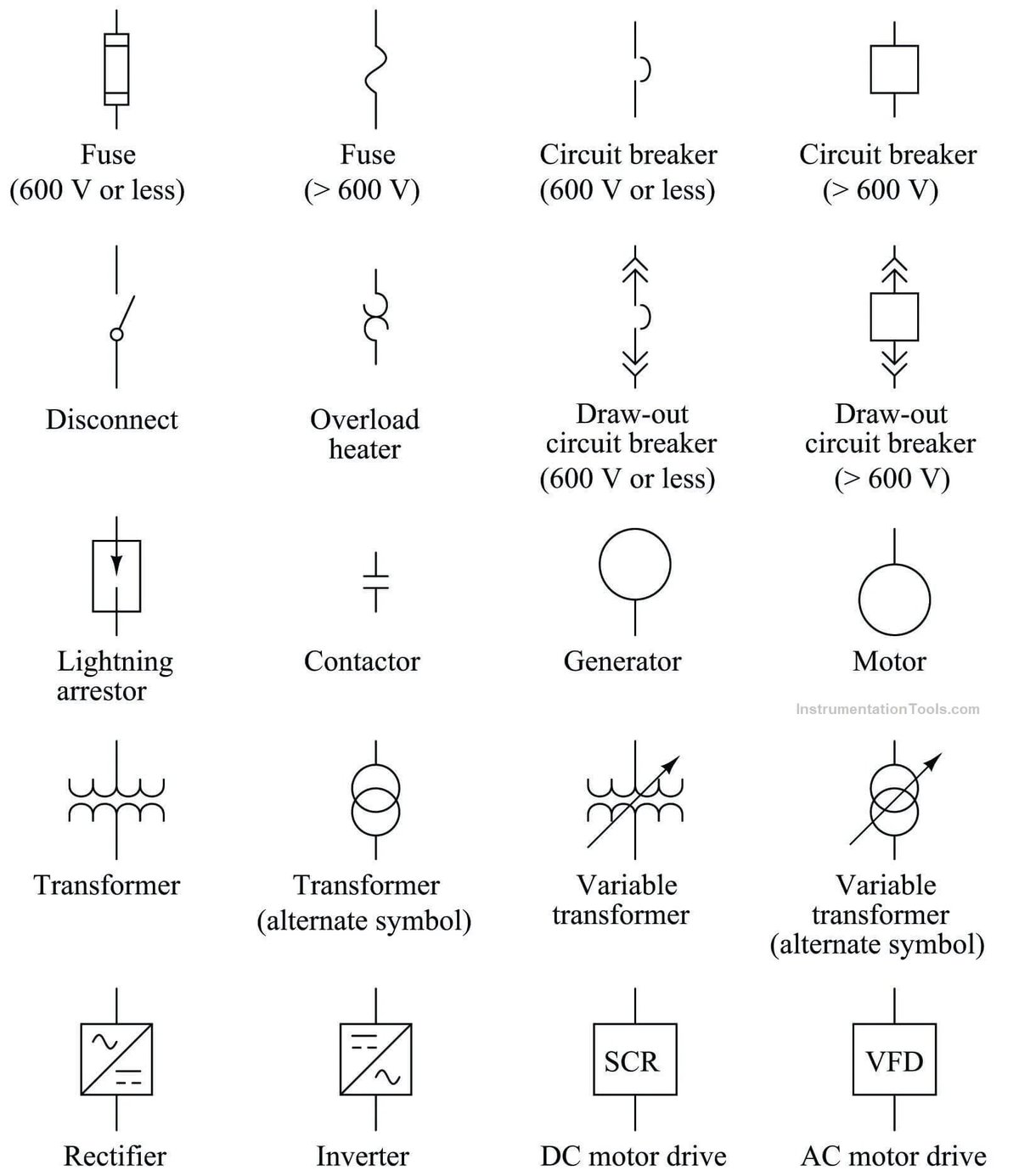
5. Protective Device Symbols: The Circuit's Guardians
These components are designed to protect the circuit and its loads from excessive current.
- Fuse: A thin rectangle with a line running through it (IEC) or a zigzag line (ANSI). A one-time-use device that melts and breaks the circuit during an overcurrent event.
- Circuit Breaker: A standard contact line with an inverted arc or a specific breaking mechanism symbol. A resettable device that automatically trips (opens) on overcurrent or fault conditions.
- Thermal Overload Relay: Two conjoined curved shapes or a specific heating element symbol. Protects motors from sustained overcurrent by opening a control contact after detecting excessive heat.
6. Passive Component Symbols: Resisting, Storing, Inducing
These components modify the flow of electricity in various ways.
- Resistor: IEC: a hollow rectangle. ANSI: a zigzag line. Used to limit or resist the flow of current.
- Variable Resistor/Potentiometer: Resistor symbol with a diagonal arrow pointing at it. Indicates adjustable resistance, often used for volume control or dimmers.
- Capacitor (Non-Polarized): Two parallel lines of equal length. Stores energy in an electric field. Can be connected in either direction.
- Capacitor (Polarized): One straight line (positive) and one curved line (negative) or a thicker bar. Requires correct polarity for connection, common in DC circuits.
- Inductor: A series of loops/coils. Stores energy in a magnetic field, often used in filters or power supplies.
7. Semiconductor & Active Device Symbols: The Brains of the Circuit
These devices control or amplify current flow, forming the basis of modern electronics.
- Diode: A triangle pointing towards a vertical line. Allows current to flow in one direction only (the triangle points in the direction of conventional current flow).
- Light Emitting Diode (LED): A diode symbol with two arrows pointing away from it, indicating light emission.
- Zener Diode: A diode symbol with small "wings" or a 'Z' shape on the vertical line. Designed to allow reverse current flow once a specific voltage is reached, used for voltage regulation.
- Transistor (NPN/PNP): Features a base, collector, and emitter with an arrow.
- NPN: Arrow points away from the base ("Not Pointing iN").
- PNP: Arrow points towards the base ("Points iN Perpetually").
These act as electrically controlled switches or amplifiers. - SCR (Silicon Controlled Rectifier): A diode symbol with a third lead (gate). It blocks current until a trigger pulse is applied to the gate, after which it conducts until the current drops below a certain level.
8. Motor & Actuator Symbols: The Circuit's Muscles
These symbols represent components that convert electrical energy into mechanical motion.
- Motor (General): A circle with 'M' inside.
- AC Motor: General motor symbol with a sine wave (~) inside.
- DC Motor: General motor symbol with a solid and dashed line underneath the 'M'.
- Solenoid Valve: A rectangle with a diagonal line, often depicted with a coil symbol. Represents an electromagnetically controlled valve that opens or closes fluid paths.
9. Meter & Indicator Symbols: The Circuit's Senses
These symbols represent devices that measure or display circuit conditions.
- Voltmeter: A circle with 'V' inside. Measures voltage across two points (always connected in parallel).
- Ammeter: A circle with 'A' inside. Measures current flowing through a circuit (always connected in series).
- Ohmmeter: A circle with 'Ω' (Omega) inside. Measures resistance (only on de-energized circuits).
- Pilot Light/Indicator Lamp: A circle with an 'X' through it, or an 'L' inside. Provides visual status, indicating whether a circuit is on, off, or in a specific state.
Reading Beyond the Symbols: Diagram Layout & Conventions
Symbols are just one part of the story. The way they're arranged and annotated gives you the full picture.
Flow Direction: The Path of Least Resistance
In most diagrams, particularly ladder diagrams common in North America, power typically flows from left to right and top to bottom. High potential (e.g., L1, 24V+) is usually on the left or top, moving towards lower potential or ground (e.g., L2, 0V) on the right or bottom. Following this convention helps you anticipate the current's journey.
Ladder Diagrams: A Rung-by-Rung Explanation
For North American industrial control circuits, ladder diagrams are king. They get their name because they resemble a ladder:
- Vertical Rails: Represent the power lines (e.g., L1 and L2 for AC, or + and - for DC).
- Horizontal Rungs: Contain the components of individual control circuits (e.g., a switch, a relay coil, a light). Each rung usually controls one specific load or function.
Reading these means following each rung independently from left to right, understanding the conditions that must be met for power to reach the components on that rung.
Wire Identification: The Color and Code Story
Wires are rarely just "wires." They often come with specific identifiers:
- Color Codes: Standardized colors indicate function (e.g., Black/Red for live, White for neutral, Green/Bare for ground in residential AC; specific color/stripe combinations in automotive).
- Abbreviations: Alphanumeric codes on the diagram near the wire (e.g., "14AWG-RD" for 14-gauge Red wire) detail gauge, insulation type, or destination.
These identifiers are crucial for physically wiring and troubleshooting.
Component Identification Codes: Your Part Number Decoder
Every component on a diagram usually has an alphanumeric code (e.g., "K1" for a relay, "M1" for a motor, "C105" for a specific capacitor). These codes refer back to a bill of materials (BOM) or a component list, allowing you to find the exact physical part and its specifications. This ensures you're installing the correct component with the right ratings.
Reference Grid/Zone Indexing: Navigating Complex Schematics
For very large, multi-page diagrams, you'll often see a grid system (like A1, B3) around the edges. Components or wire ends might have a notation like "to D5," indicating where that wire or component continues on another part of the diagram or another page. This is your GPS for complex blueprints.
Connection Points: The Junctions of the System
Diagrams will also detail how wires connect to each other or to multi-pin connectors:
- Splices: Points where multiple wires join are clearly marked.
- Multi-pin Connectors: These are often shown with a block representing the connector and numbered pins, sometimes with a physical pinout diagram or table to guide connections. Knowing these pin assignments is vital for automotive and electronics work.
Your Step-by-Step Guide to Tracing a Circuit
Understanding symbols is great, but applying that knowledge to trace a circuit path is where the real skill lies. This methodical approach is your superpower for troubleshooting and verification.
- Identify the Power Origin: Start at the primary power source. This could be a battery (in a vehicle), a mains supply line (L1/L2 in a home or factory), or a power supply output. This is where the current begins its journey.
- Follow Protective Devices: From the power source, current almost always flows through a protective device first – a fuse or a circuit breaker. Confirm that this device is in its "closed" (current-passing) state. If it's open, your circuit won't work!
- Proceed to the Control Device(s): Next, trace through any switches, relay contacts, sensors, or other components designed to control the flow of power. For power to continue, these control devices must be in their "active" or "closed" state (e.g., a pushbutton pressed, a relay coil energized, a sensor detecting something). Remember their "normal" state when evaluating.
- Flow to the Load: Once power has successfully navigated the control section, it reaches the "load"—the component that performs work. This could be a light bulb, a motor, a solenoid, or an electronic module. Ensure current is flowing into the correct terminals of the load, especially for polarized components like LEDs or DC motors.
- Terminate at Ground (or Return Path): Finally, trace the circuit back from the load to the common return path, which is usually chassis ground, earth ground, or the negative terminal of the power source (like the L2/neutral line in AC circuits). This completes the electrical loop.
By systematically following this path, you can confirm correct circuit design, identify where power should be, and diagnose faults by pinpointing exactly where the current path is broken or interrupted. It's the ultimate method for understanding wiring diagram symbols in action.
Context Matters: How Wiring Diagrams Differ
While the fundamental principles remain, the specific conventions, priorities, and details within wiring diagrams vary significantly depending on the application.
Automotive Diagrams: The World on Wheels
Vehicle wiring diagrams are a unique beast. They emphasize:
- Physical Harnesses and Connectors: Diagrams often show multi-pin connectors, their pin numbers, and how they physically route within a wiring harness. This is critical for tracing faults in complex vehicle systems.
- Specific Wire Color Codes: Automotive manufacturers use intricate color codes and stripe combinations (e.g., Red with Black stripe, Green with White stripe) that are unique to their brand or model, indicating specific circuit functions.
- Environmental Ratings: Wires and components are designed for harsh conditions, with temperature ratings often from -40°C to well over 100°C.
- Low-Voltage DC Systems: Vehicles primarily use 12V or 24V DC systems, so diagrams focus on DC sources, batteries, and ground connections.
- Highly Stranded Copper Wire: To withstand constant vibration, automotive wires are extremely flexible, a detail not often shown but important to remember when working.
Residential/Commercial Building Diagrams: The Structure of Power
Building electrical plans, often part of architectural blueprints, focus on different aspects:
- Physical Location: Diagrams show where outlets, switches, light fixtures, and panels are physically located within a building structure.
- Standardized Wire Colors: In AC systems, specific wire colors are standard (e.g., Black/Red for live/hot, White for neutral, Green/bare for ground).
- Conduit Runs: Diagrams may illustrate conduit paths for wire routing, especially in commercial or industrial settings where wires are protected within pipes.
- Higher Voltage AC Systems: These diagrams deal with 120V, 240V, or higher AC voltages, emphasizing safety devices like GFCI/AFCI breakers and proper grounding.
- Load Schedules: Often include tables detailing the electrical load (in watts or amps) of various circuits.
The key distinction is that automotive diagrams prioritize the electrical connection and harness routing, while building diagrams often combine electrical schematics with physical layout.
Common Misconceptions and Pitfalls to Avoid
Even experienced hands can slip up. Here are some common mistakes to watch out for:
- Assuming Standards: Never assume whether a diagram uses IEC or ANSI symbols. Always find the legend. This is the number one cause of misinterpretation.
- Ignoring the "Normal" State: Forgetting that switches and relays are drawn de-energized leads to incorrect logic interpretations, especially during troubleshooting.
- Overlooking Wire Numbers/Labels: Skipping alphanumeric wire identifiers can lead to connecting the wrong wires, especially in complex control panels.
- Neglecting Ground Paths: A complete circuit requires a return path to the source. Overlooking a ground connection on the diagram means your circuit won't work in reality.
- Misinterpreting Crossings: Believing wires crossing without a dot are connected is a fundamental error. If there's no dot, they are separate.
- Relying on Memory for Critical Circuits: Even if you think you know a symbol, for safety-critical or complex circuits, double-check the legend.
Mastering the Language: Key Takeaways for Effective Interpretation
Learning to read wiring diagrams is a skill that improves with practice and a methodical approach. Here's how to build your expertise:
- Symbols are a Precise Language: Each symbol has a specific, unambiguous meaning. Treat them as such, like words in a technical manual.
- Identify the Standard First: The very first step is always to determine if the diagram uses IEC, ANSI, or another specific standard. Your entire interpretation hinges on this.
- "Normal State" is Your Baseline: Internalize that all control devices (switches, relays) are depicted in their unactivated, at-rest position. This is crucial for understanding how the circuit reacts when energized.
- Learn by Category, Not Just Rote: Instead of trying to memorize hundreds of individual symbols, learn the function of each category (power, control, protection, load). This builds a framework for understanding new symbols.
- Understand Logical vs. Physical: Distinguish between a schematic (how the circuit works logically) and a wiring diagram (how to build it physically, including wire colors, connectors, and routing). Both are crucial.
- Practice, Practice, Practice: The best way to become proficient is to regularly trace circuits, starting with simple ones and gradually moving to more complex designs. Grab an old appliance manual, find a vehicle repair guide, or even look up basic electronic circuits online.
Your Next Steps on the Wiring Journey
You've now got a robust foundation in the symbols and principles that govern wiring diagrams. This isn't just theoretical knowledge; it's a practical skill that empowers you to diagnose, build, and understand the electrical world around you.
To solidify your understanding, here’s what to do next:
- Find a Diagram: Locate a simple wiring diagram for a household appliance, a car accessory, or a basic electronic project.
- Identify the Standard: Look for a legend or key to confirm if it’s IEC, ANSI, or something else.
- Trace a Path: Pick a power source, and systematically trace the current's flow through protective devices, control components, to a load, and back to ground.
- Quiz Yourself: Point to random symbols and try to identify their function and "normal" state.
With consistent practice, the "hieroglyphs" will transform into a clear, concise language, opening up a world of electrical understanding. Your journey into confident circuit analysis has only just begun!